| The QRS complex: ECG features of the Q | 您所在的位置:网站首页 › deep onecg › The QRS complex: ECG features of the Q |
The QRS complex: ECG features of the Q
|
The QRS complex (ventricular complex): normal and abnormal configurations and intervals
A complete QRS complex consists of a Q-, R- and S-wave. However, all three waves may not be visible and there is always variation between the leads. Some leads may display all waves, whereas others might only display one of the waves. Regardless of which waves are visible, the wave(s) that reflect ventricular depolarization is always referred to as the QRS complex. Naming of the waves in the QRS complex:Naming of the waves in the QRS complex is easy but frequently misunderstood. The following rules apply when naming the waves: A deflection is only referred to as a wave if it passes the baseline. If the first wave is negative then it is referred to as Q-wave. If the first wave is not negative, then the QRS complex does not possess a Q-wave, regardless of the appearance of the QRS complex. All positive waves are referred to as R-waves. The first positive wave is simply an "R-wave" (R). The second positive wave is called "R-prime wave" (R'). If a third positive wave occurs (rare) it is referred to as "R-bis wave" (R''). Any negative wave occurring after a positive wave is an S-wave. Large waves are referred to by their capital letters (Q, R, S), and small waves are referred to by their lower-case letters (q, r, s).Figure 5 shows examples of naming of the QRS-complex.  Figure 5. Naming of the QRS complex.
Net direction of the QRS complex Figure 5. Naming of the QRS complex.
Net direction of the QRS complex
The QRS complex can be classified as net positive or net negative, referring to its net direction. The QRS complex is net positive if the sum of the positive areas (above baseline) exceeds that of the negative areas (below baseline). Refer to Figure 6, panel A. These calculations are approximated simply by eyeballing. Panel B in Figure 6 shows a net negative QRS complex, because the negative areas are greater than the positive area.  Figure 6. Approximations of the net direction of the QRS-complex. The positive areas are yellow and the negative areas are green.
Electrical vectors that engender the QRS complex Figure 6. Approximations of the net direction of the QRS-complex. The positive areas are yellow and the negative areas are green.
Electrical vectors that engender the QRS complex
Depolarization of the ventricles generate three large vectors, which explains why the QRS complex is composed of three waves. It is fundamental to understand the genesis of these waves and although it has been discussed previously a brief rehearsal is warranted. Figure 7 illustrates the vectors in the horizontal plane. Study Figure 7 carefully, as it illustrates how the P-wave and QRS complex are generated by the electrical vectors. 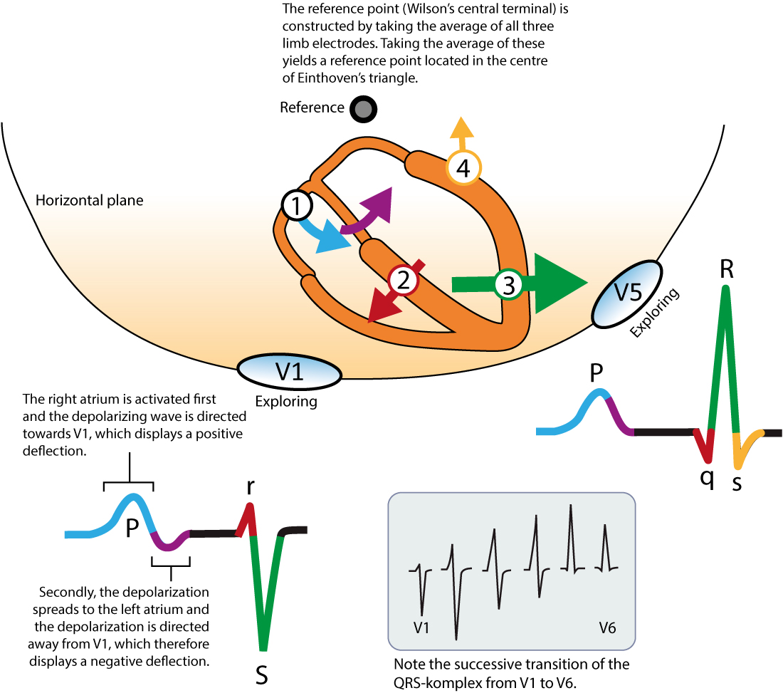 Figure 7. The heart's main electrical vectors seen from the horizontal plane. V1 and V5 are exploring electrodes and the reference is composed of the average of the electrodes placed on the limbs (this reference is called Wilson's central terminal). Inspired by MacFarlane et al (Springer, Comprehensive Electrocardiology, 2010). Figure 7. The heart's main electrical vectors seen from the horizontal plane. V1 and V5 are exploring electrodes and the reference is composed of the average of the electrodes placed on the limbs (this reference is called Wilson's central terminal). Inspired by MacFarlane et al (Springer, Comprehensive Electrocardiology, 2010).
Note that the first vector in Figure 7 is not discussed here as it belongs to atrial activity. The second vector: the ventricular (interventricular) septumThe ventricular septum receives Purkinje fibers from the left bundle branch and therefore depolarization proceeds from its left side towards its right side. The vector is directed forward and to the right. The ventricular septum is relatively small, which is why V1 displays a small positive wave (r-wave) and V5 displays a small negative wave (q-wave). Thus, it is the same electrical vector that results in an r-wave in V1 and q-wave in V5. The third vector: the ventricular free wallThe vectors resulting from activation of the ventricular free walls is directed to the left and downwards (Figure 7). The explanation for this is as follows: The vector resulting from activation of the right ventricle does not come to expression, because it is drowned by the many times larger vector generated by the left ventricle. Thus, the vector during activation of the ventricular free walls is actually the vector generated by the left ventricle. Activation of the ventricular free wall proceeds from the endocadrium to the epicardium. This is because the Purkinje fibers run through the endocardium, where they deliver the action potential to contractile cells. The subsequent spread of the action potential occur from one contractile cell to another, starting in the endocardium and heading towards the epicardium.As evident from Figure 7, the vector of the ventricular free wall is directed to the left (and downwards). Lead V5 detects a very large vector heading towards it and therefore displays a large R-wave. Lead V1 records the opposite, and therefore displays a large negative wave called S-wave. The fourth vector: basal parts of the ventriclesThe final vector stems from activation of the basal parts of the ventricles. The vector is directed backwards and upwards. It heads away from V5 which records a negative wave (s-wave). Lead V1 does not detect this vector. Implications and causes of wide (broad) QRS complexProlongation of QRS duration implies that ventricular depolarization is slower than normal. The QRS duration is generally |
【本文地址】